Arma Design Studio
CAD/CAM Software
Tube Frame Design and Manufacturing Software
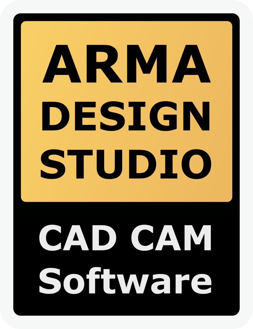
ADS opens with a menu bar at the top for common features and settings, a collapsible toolbar on the right for interacting with the scene and adding or modifying objects, context-relevant tool buttons in the footer, and an object tree list, selection list, and properties panel on the right.
Navigation is done using the default Move Object tool. Click and drag on the scene with the Command key held down to pan and the Option key to rotate. Click an object to select it, and hold the Shift key to add or remove objects from the selection. If multiple objects can be selected, they will appear in the Selection window on the right side of the screen. Use the mouse wheel or trackpad to zoom in and out.
Directions for common actions are listed on screen in the upper-left corner. Press the `H` key to hide them.
Add objects to the scene using the object tools on the left side of the application. For example, click the Create Cube tool and then click and drag in the scene to set the size of the cube. Click and release on the scene background to deselect the current object. Press the Escape key to deselect the active tool. Click a scene object to open the properties panel, which allows you to set the location, orientation, scale, and size of the object. The Delete key will remove the object from the scene.
Objects in the scene are listed in the tree list on the right side of the screen. You can add objects as children of other objects for organization, and some objects also affect the behavior of their parent objects.
To get started quickly, try loading a template project by clicking the red rocket labeled Getting Started and choosing a project to import. If you need help, contact us by email or use the in-app chat feature and we will respond as soon as possible.
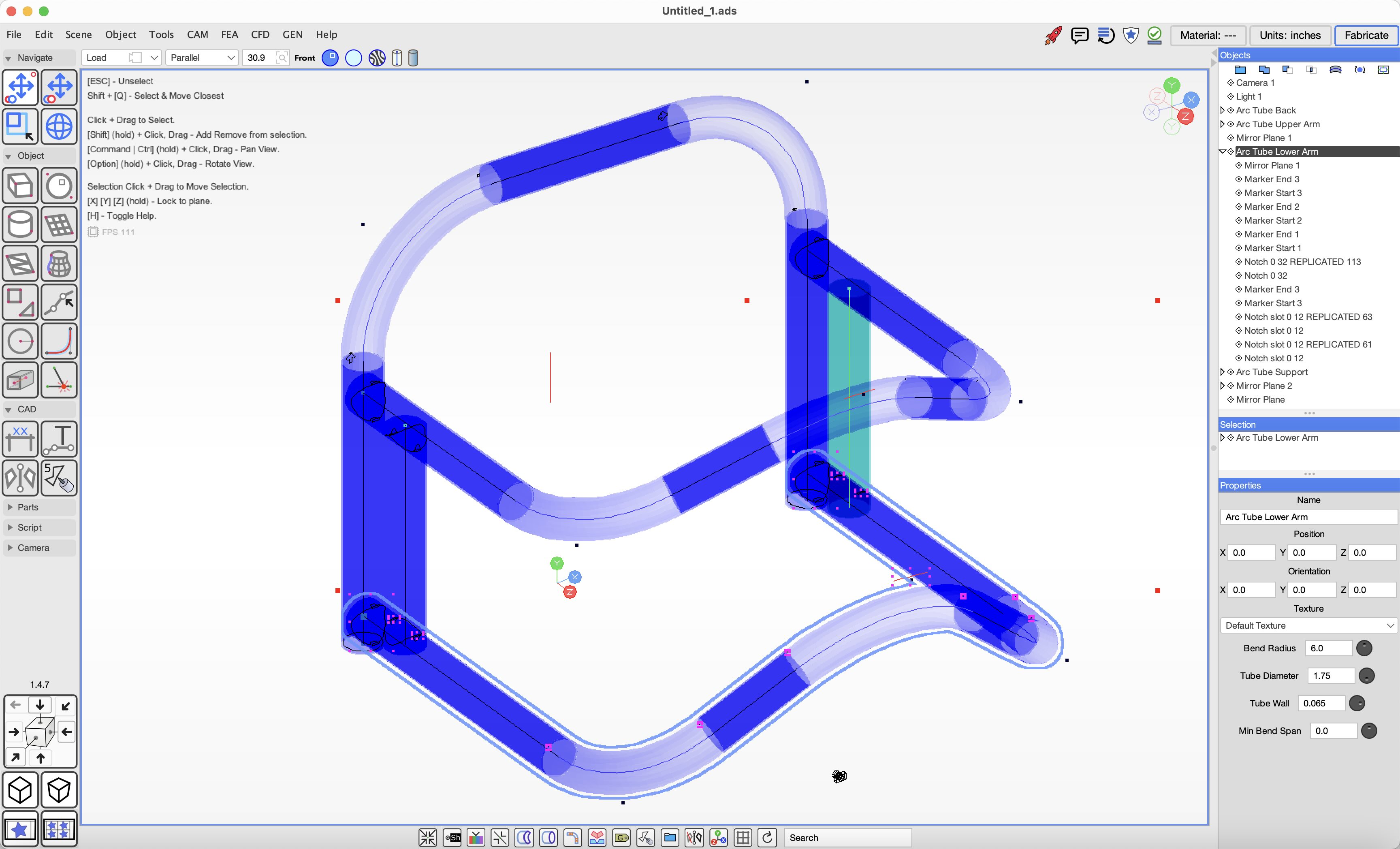
Tip: We recommend adding most objects in the front-facing view. This makes the object orientation match the scene coordinates and simplifies most editing later.
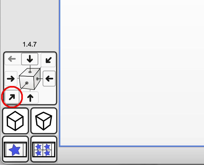 You can set the front facing view by clicking on the navigation arrow for the front face or by
selecting the Front view in the drop down.
You can set the front facing view by clicking on the navigation arrow for the front face or by
selecting the Front view in the drop down.
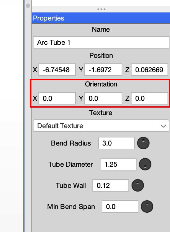
 Objects created from the front view will have orientation values of zero. This means that when you edit an object, the orientation will remain consistent with the scene.
Launch ADS, click the File menu, choose Import, and select one of the supported file formats.
If you are importing a tube-frame model, we recommend OBJ format or, if that is not available, STEP.
Once you import a model, the geometry will be placed in a Triangle Mesh object.
You can convert mesh geometry to the round tube object type using the `Tools` > `Tube` > `Get Arc Tube from Mesh` menu item.
Importing large mesh objects such as scanned models will usually benefit from these common functions.
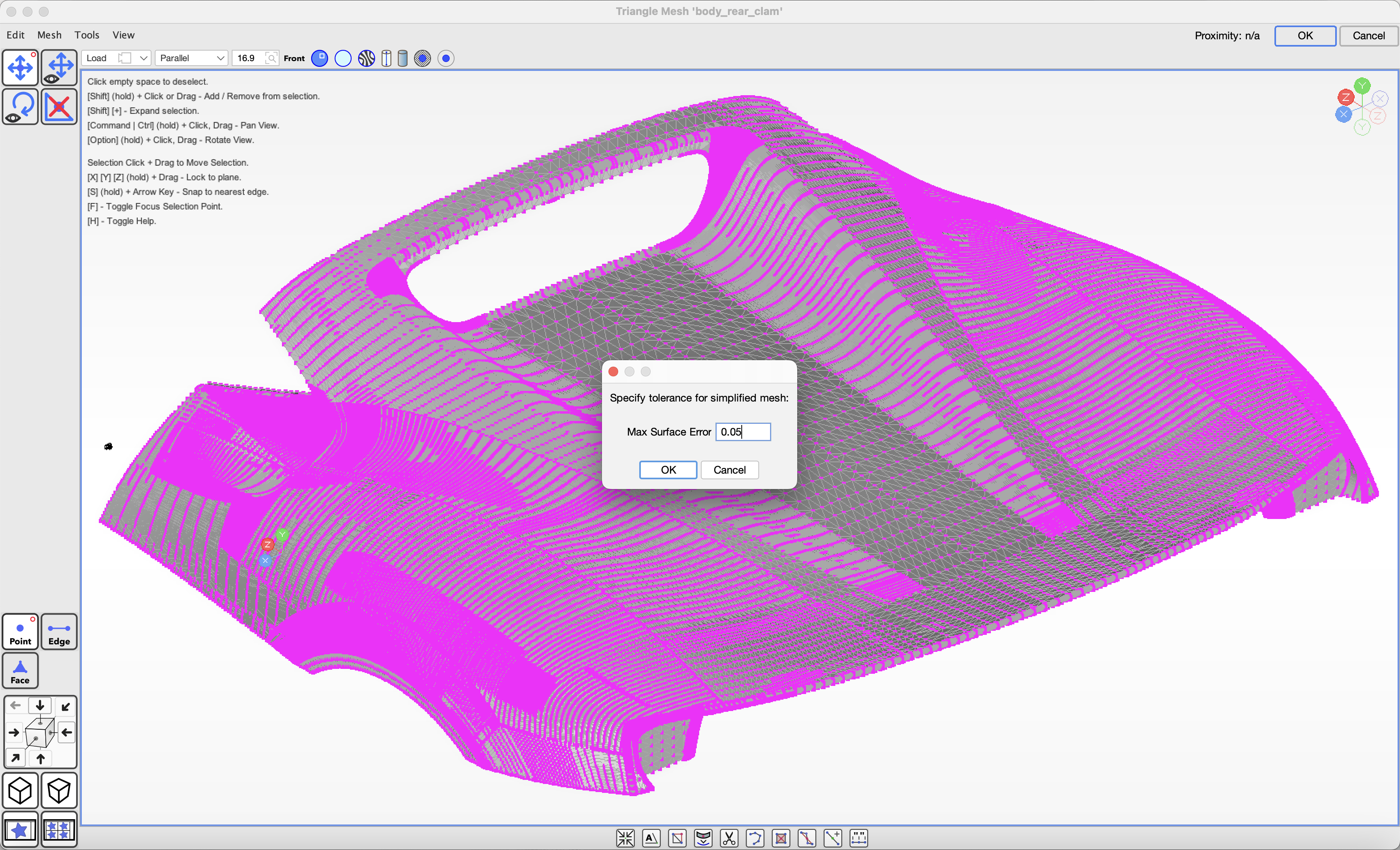
If the mesh contains too much detail and it affects performance, double-click the mesh object to edit it,
use the `Select and Move` tool to select the desired mesh area, then choose the `Mesh` > `Simplify Selection` menu item.
Enter the minimum tolerance to maintain and click OK to reduce the mesh detail.
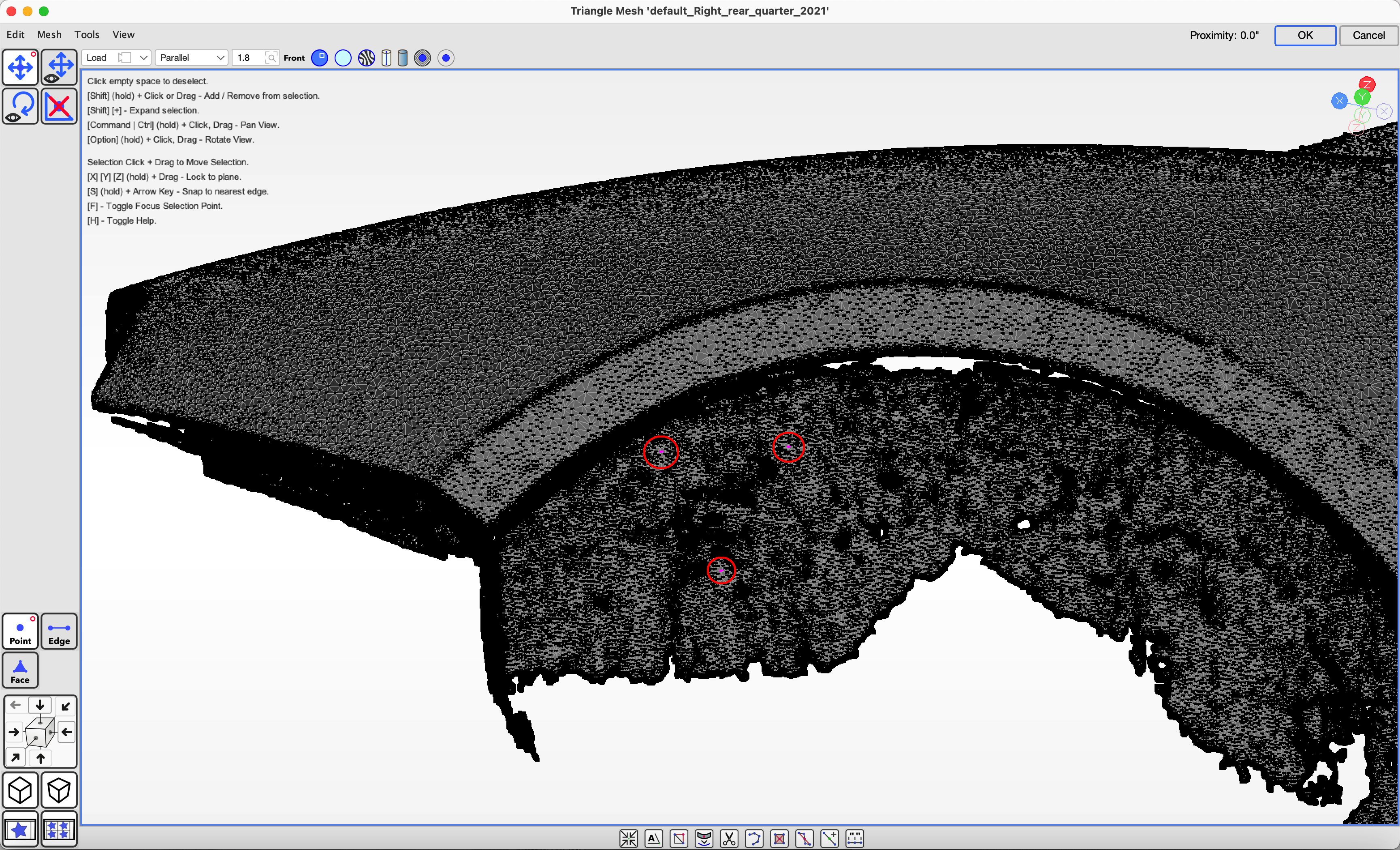
If you are importing a scanned model that is not oriented flat and the scan contains three points you know are on plane you can select them
and choose the `Tools` menu > `Rotate to level by Selection`, which will rotate the object to level the selection. You can then rotate the object to orient it to the front.
We recommend keeping backups of your working files on separate media, as well as making frequent saves while working with ADS.
ADS also makes a daily backup in a folder named after the project file, and backups are kept for thirty days. In the event that a rare bug corrupts your project, a recent backup can be used to recover some progress.
Currently, the suggested method for working on ADS projects in a team is to use a network drive and coordinate so that only one person edits a file at a time. When opening a file that is already open by another user, ADS will notify you with a dialog.
Purchase license keys to unlock features.
License keys for features can be purchased from our website. Keys are tied to your email address, so be sure to keep track of the
email address you use for payment.
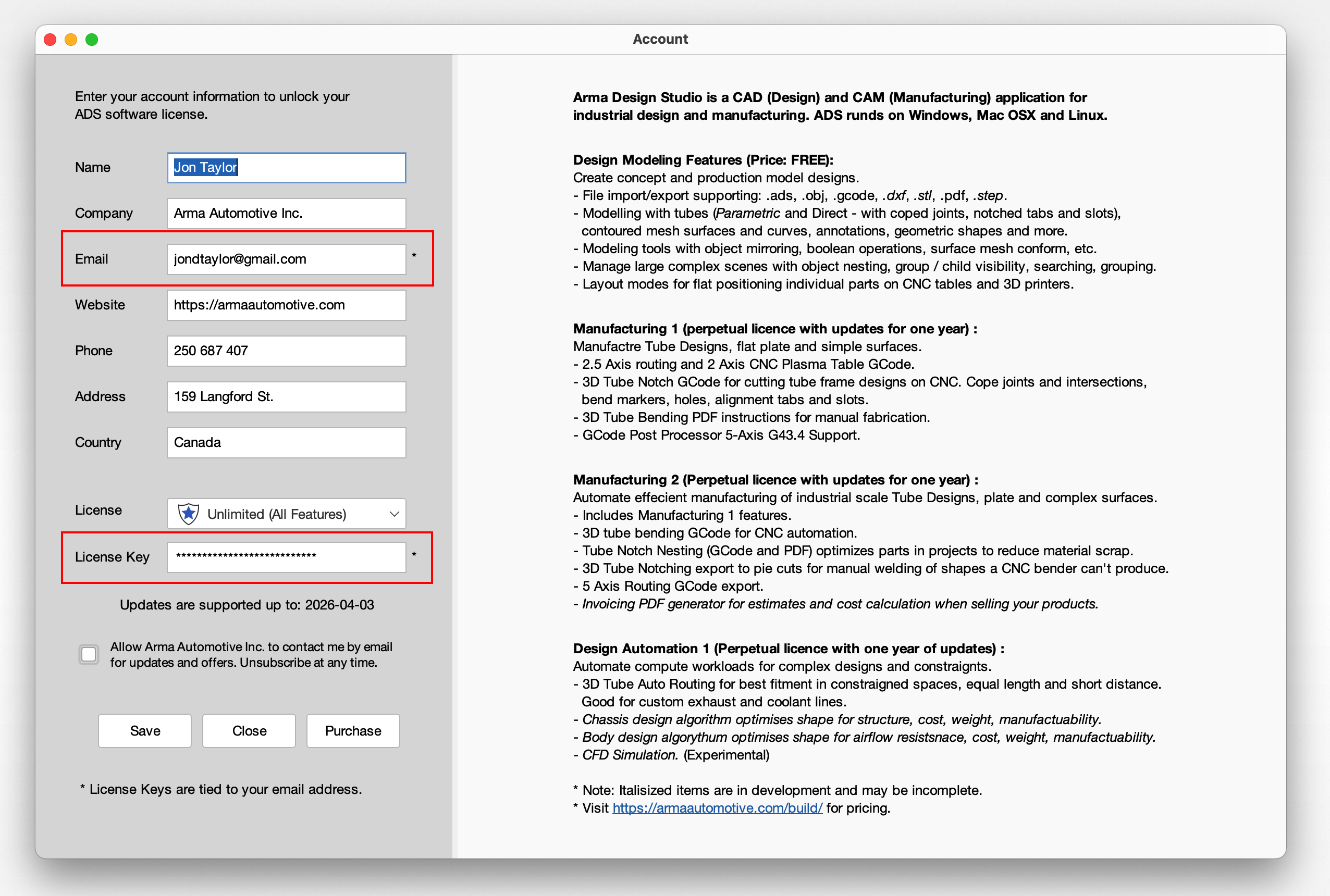
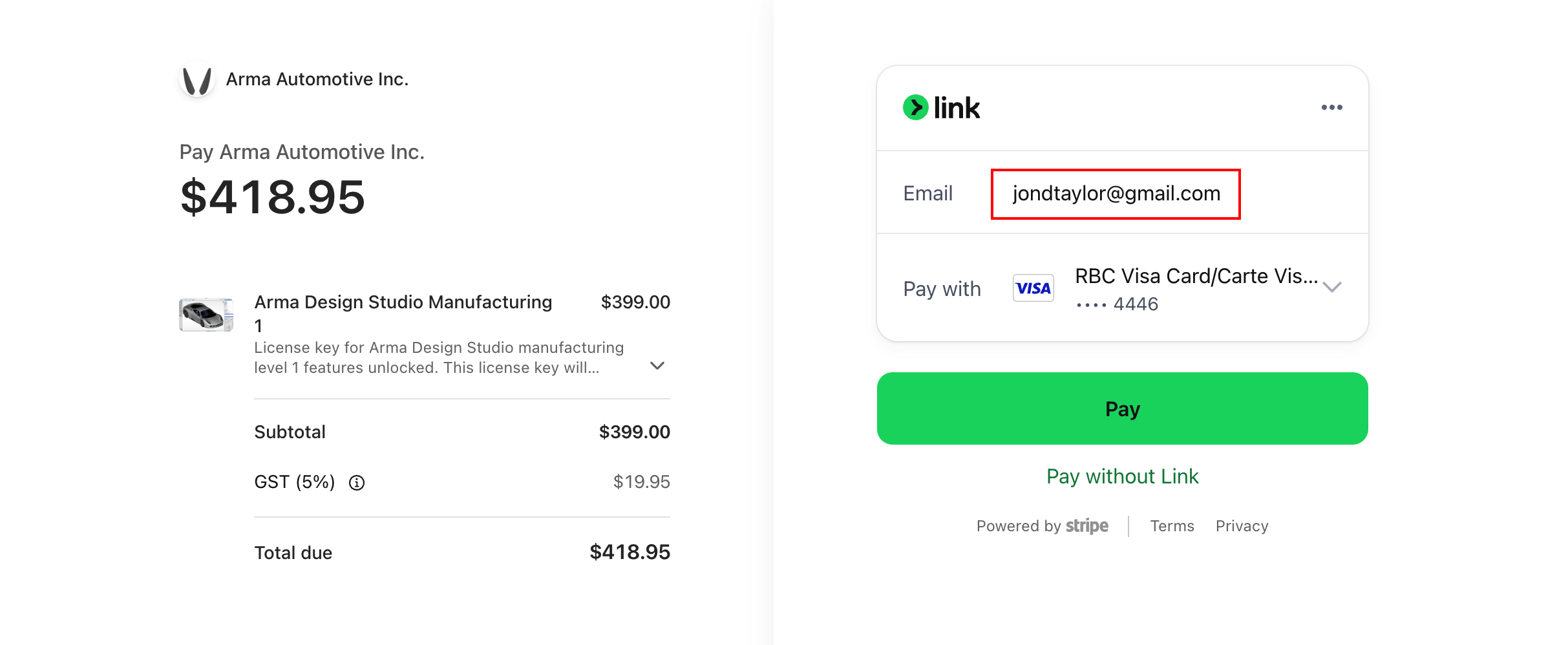 In ADS, click the `File` > `Account` menu item and enter the same email address and the license key you received by email.
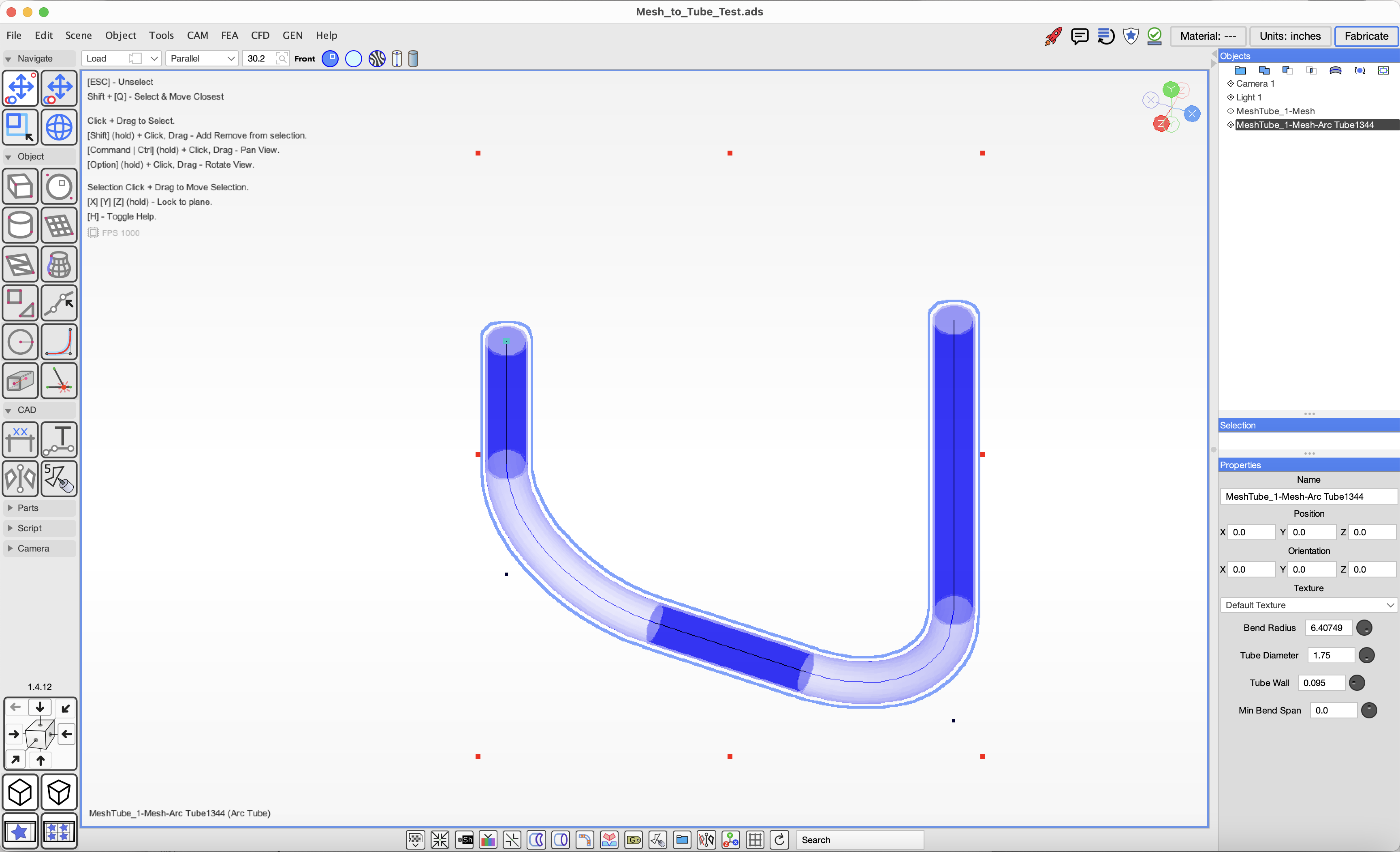
Model round tube structures by converting imported tube mesh objects or drawing tubes with the Arc Tube tool.
To convert a mesh object to arc tube objects, select the mesh object, then choose the `Tools` > `Tube` > `Get Arc Tube from Mesh` menu item. If the conversion does not work correctly the Create Arc Tube tool will be needed to correct the incomplete sections.
To create new round tube designs, use the `Create Arc Tube` tool by clicking the tool and then clicking in the scene where the ends and bend points will be.
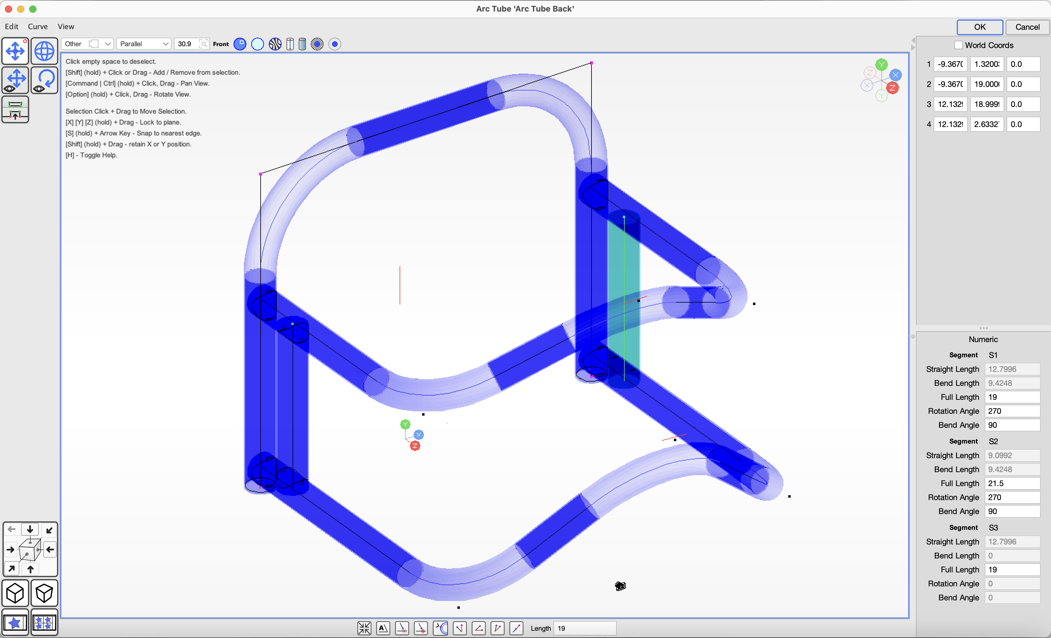
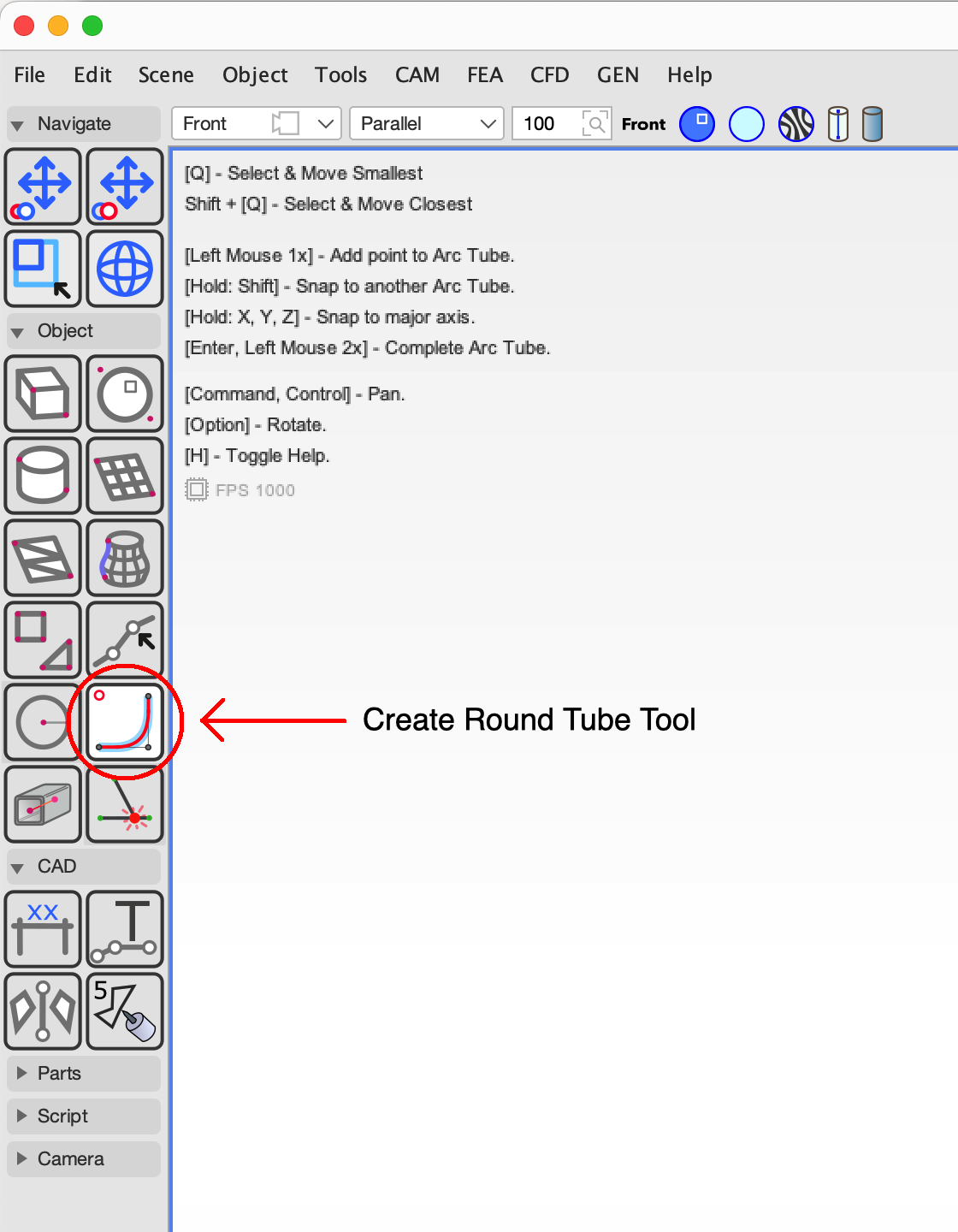 Press Enter or double-click in the scene to complete the object. Select the object and click the `Object` > `Edit Object` menu item, or double-click the object to
edit it. In the properties pane, you can set the diameter, wall thickness, and bend radius, or choose a material from a list by clicking the Material button at
the top right of the screen. When editing the object, you can move the points or enter numeric values to modify its shape.
Press Enter or double-click in the scene to complete the object. Select the object and click the `Object` > `Edit Object` menu item, or double-click the object to
edit it. In the properties pane, you can set the diameter, wall thickness, and bend radius, or choose a material from a list by clicking the Material button at
the top right of the screen. When editing the object, you can move the points or enter numeric values to modify its shape.
Join arc tubes with an offset using the `Create Attachment` tool. Select the Attachment tool and click an Arc Tube object to add the attachment.
Notching is added to an Arc Tube (round tube) as a Tool Path object, which is a child of the tube.
The Tool Path pattern wraps the surface of the tube and marks where cuts are to be made.
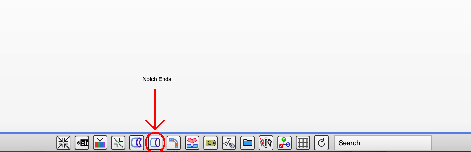
You can add notches to the ends of a tube by selecting it and clicking the Notch Ends button in the footer bar, or by choosing the
menu item `Tools` > `Tube Notching` > `Auto Notch Tube Ends Outer`. You can modify the notch using the editor.
Tubes that intersect another tube can be notched to the joint by selecting the tube to notch and clicking the Notch Intersection button in the footer bar.
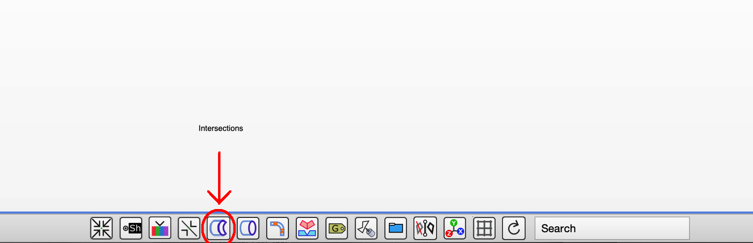 You can also choose the menu item `Tools` > `Tube Notching` > `Notch Angled Tube Intersections`.
Tabs and slots are a feature of tubes and notches that create an interlocking joint, helping lock fitment into the correct location.
Click a Tool Path object that is a child of a tube intersecting another tube, then click the Tab Slots button.
Tabs will be added to the notch Tool Path, and slots will be added to the intersecting tube object. If the geometry does not look correct, you may need to make small adjustments using the editor and notify us of any bugs.
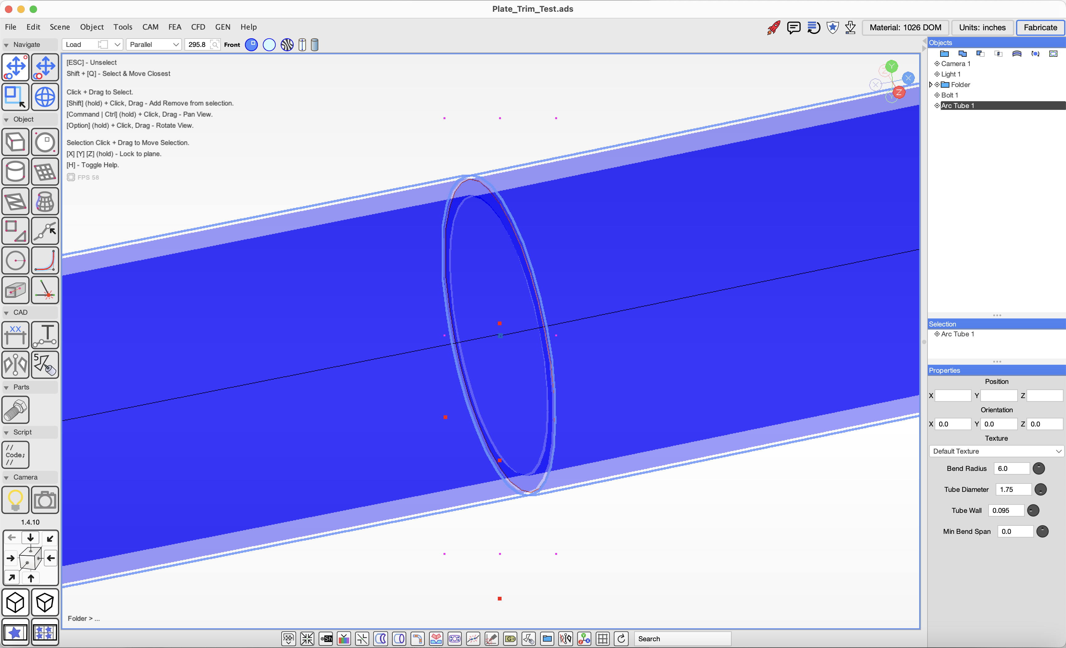
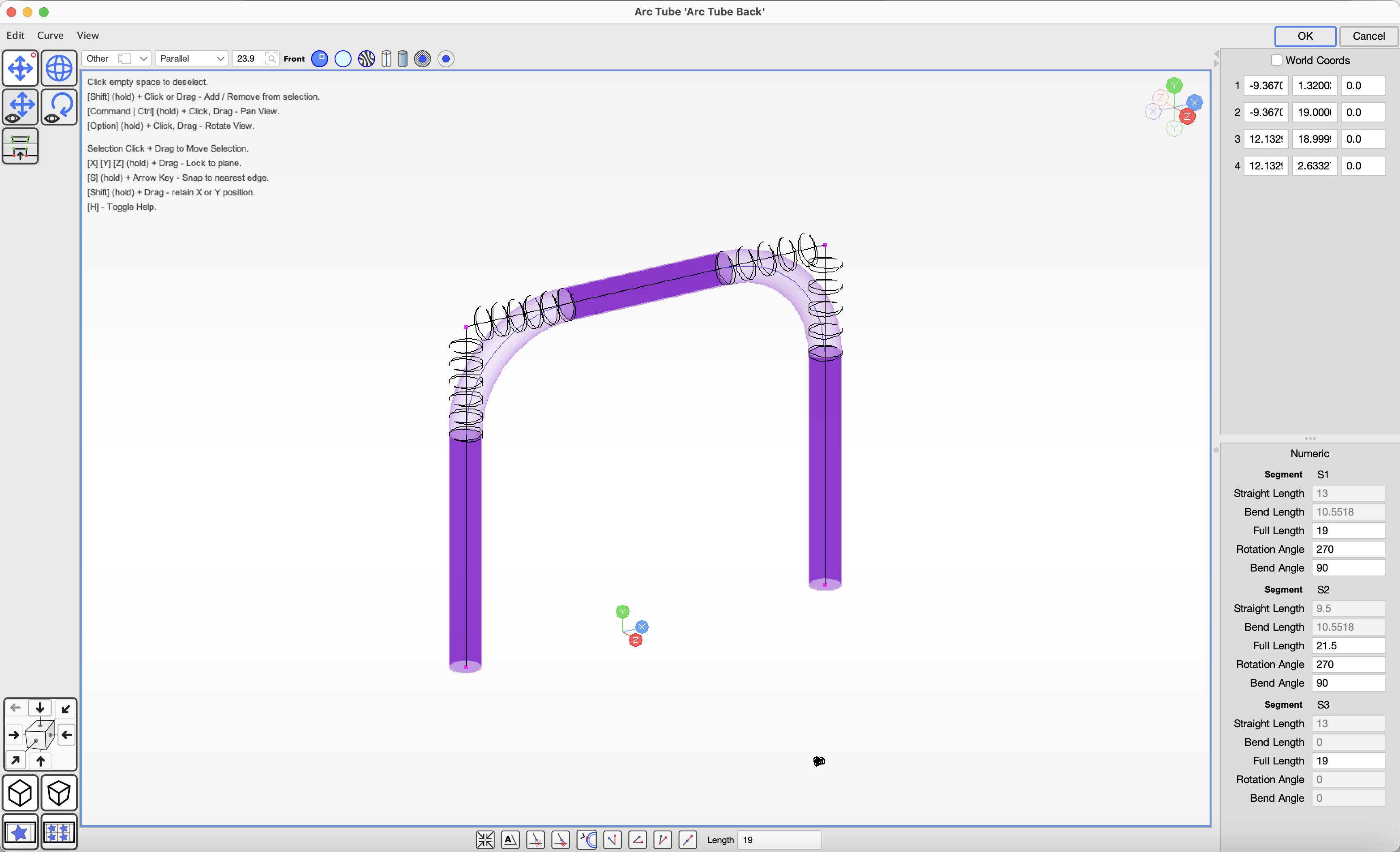
Round Tube (Arc Tube) can be modeled on screen and edited numerically with bends.
The tube properties define the bend radius, which affects the geometry of the tube.
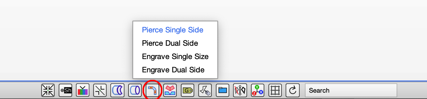
You can mark bend locations on a tube using the `Bend Markers` button in the footer bar.
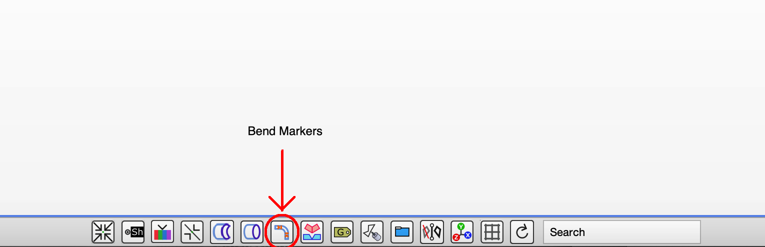
If your CNC tube notcher can draw or engrave the marker locations on the tube, choose `Engrave Single Side`. If your notcher does not have an engraver, you can choose 'Pierce Single Side'.
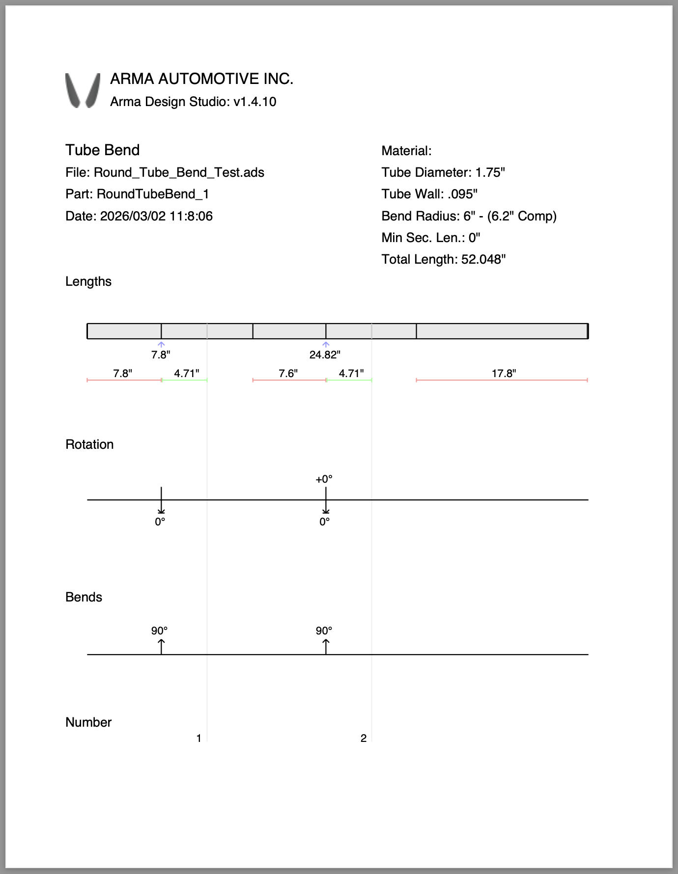
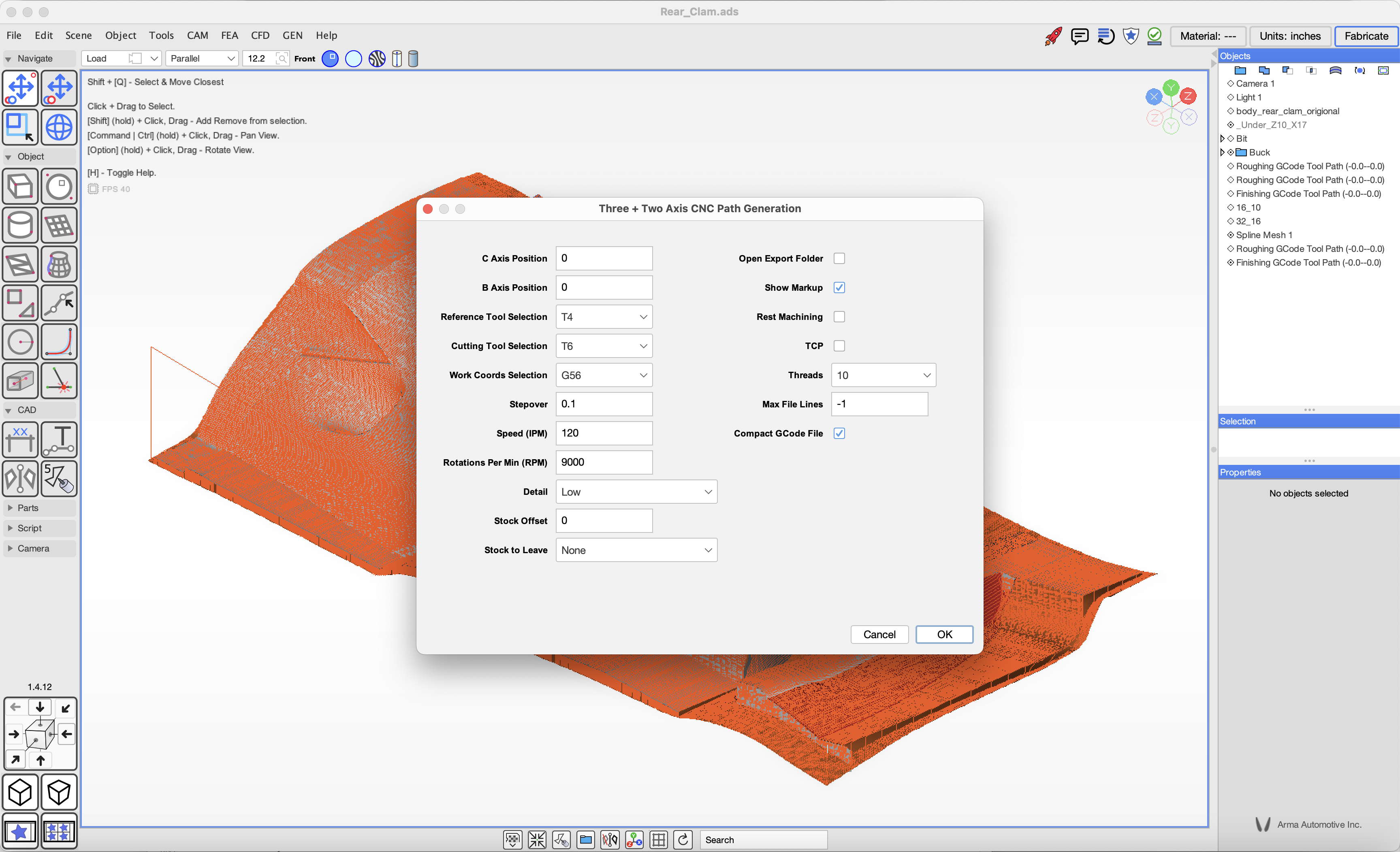
Once you have modeled your tube project, you can fabricate it by exporting CNC files using the menu items:
`CAM` > `Export Arc Tube Bend GCode` and `CAM` > `Export Arc Tube Bend PDF`.
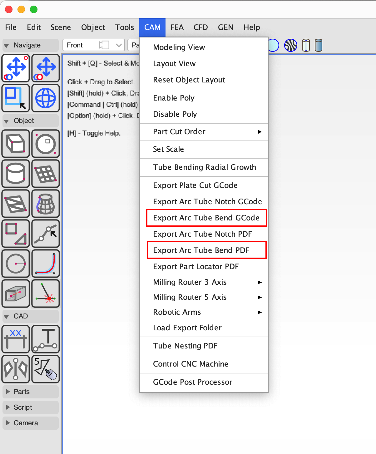
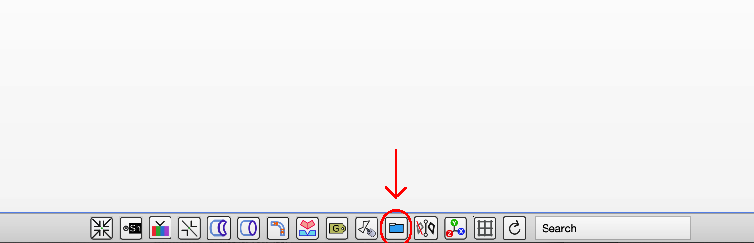
Exported files are added to a folder in your project directory. Open this folder by clicking the `Files` footer bar button.
If you do not have a CNC tube bender, you can print manual bending instructions from ADS.
Understanding radial growth: metal tube will spring back to some degree after bending, and ADS automatically compensates the bend locations to correct for this growth so your parts remain accurate.
When bending with a die of a given size, the actual tube bend radius will expand when the tube springs back. This means that the bend start and end points need to take this expansion into account, and ADS automatically does this.
Our Arma CNC Tube Bender kit automatically compensates for springback, and ADS compensates for radial growth of the tube, but any other bender will also need to compensate for springback in some form.
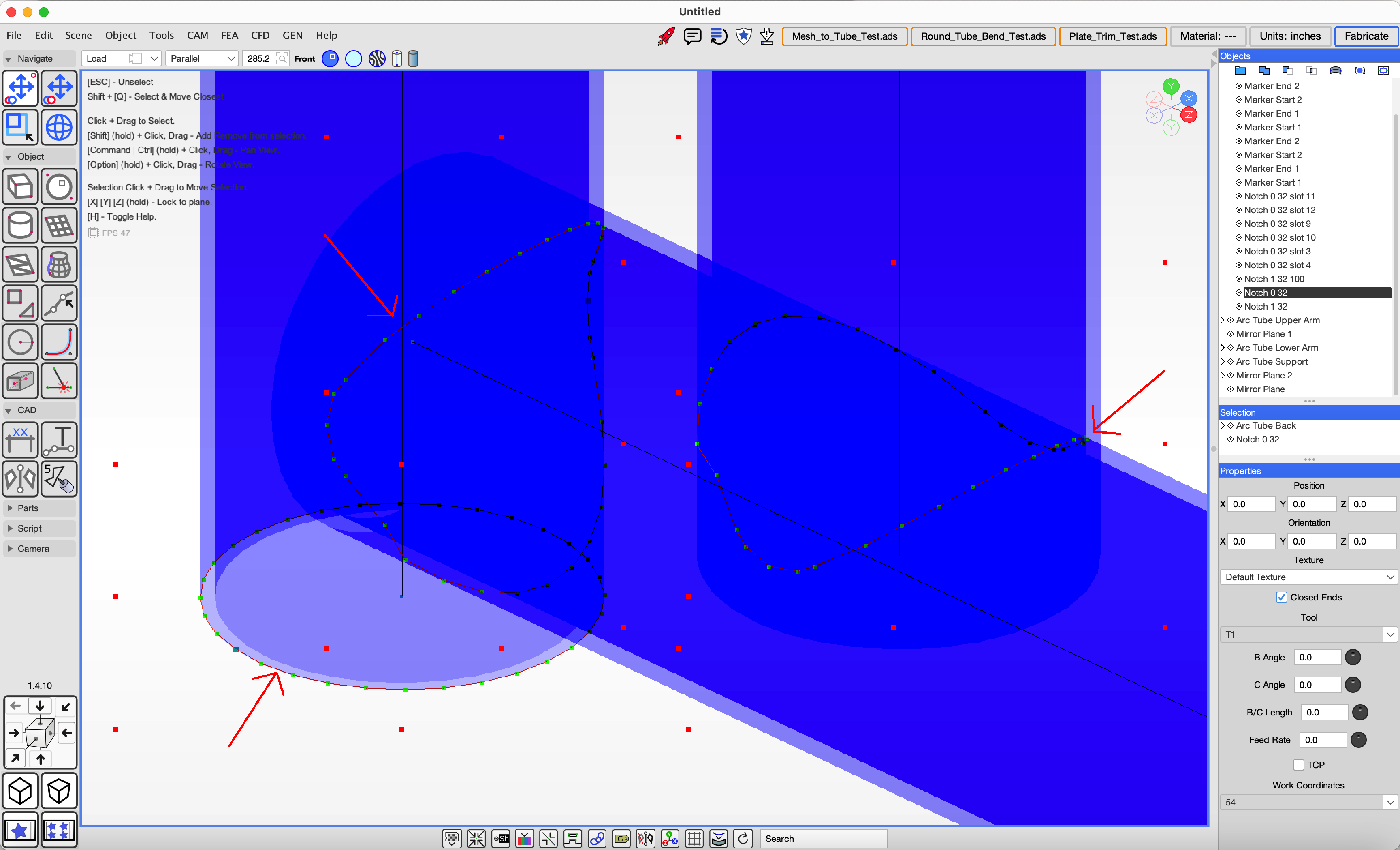
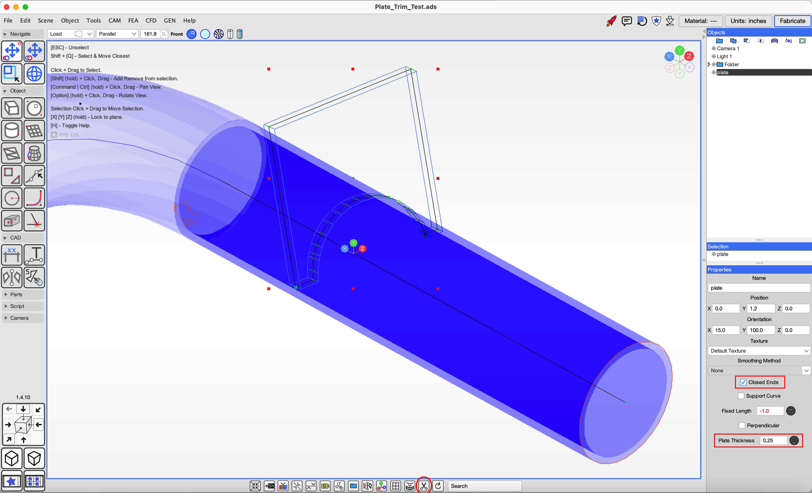
Flanges are metal plates cut to join with tube for many types of mounts. Plate can be drawn in ADS using the `Create Polygon` or `Create Curve` tool as long as: 1) the Closed Ends attribute is set 2) the Plate Thickness attribute is set and 3) the plate points are flat on a plane so they can be cut from sheet metal. The plate will appear as a wireframe rendering in ADS.
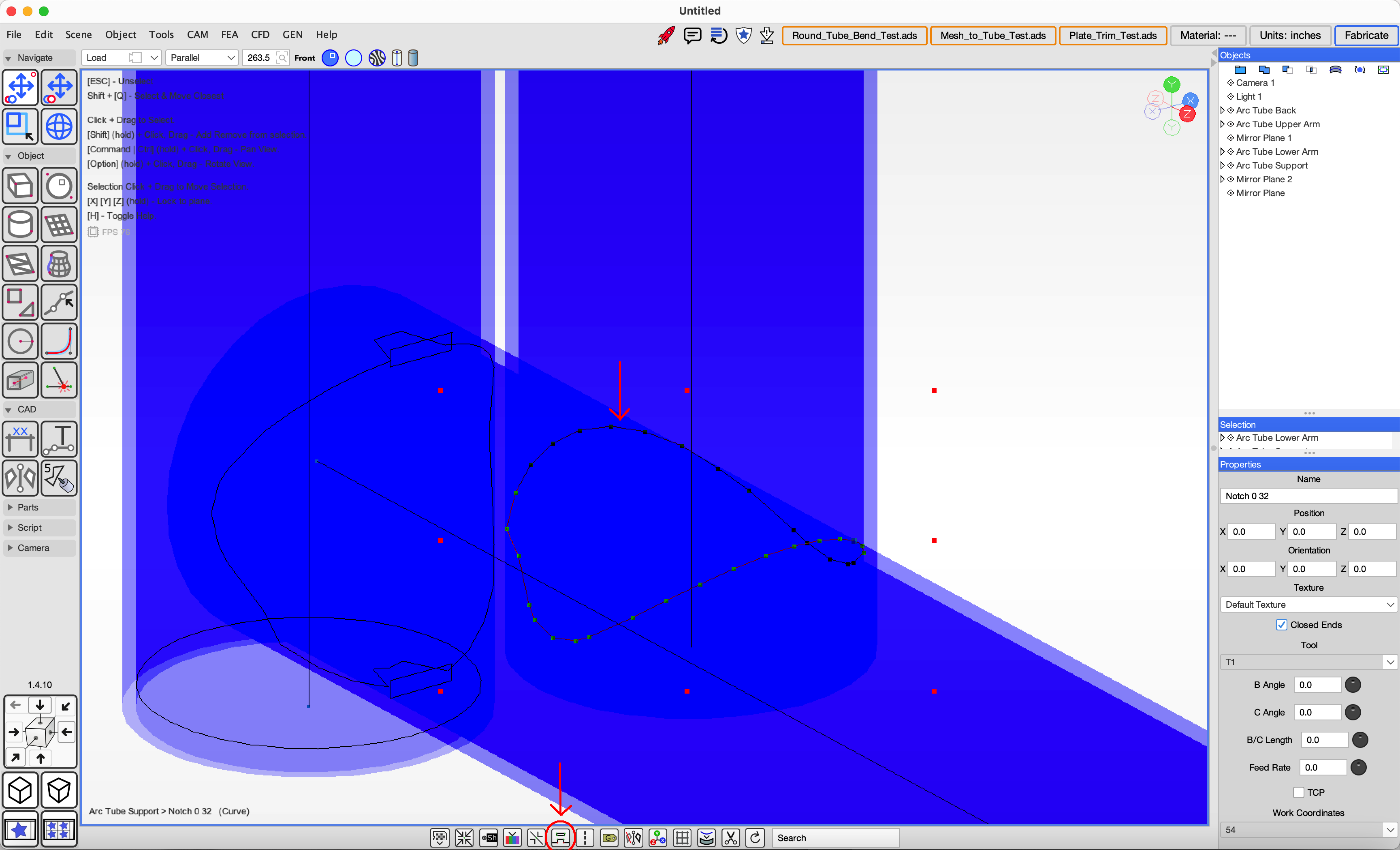
To notch a plate cutout around a tube, select the plate that intersects with a tube and click the Cut icon in the footer bar.
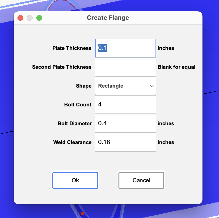
You can create flanges that join two tubes by selecting them and clicking the Flange button in the footer bar.
Choose the desired properties.
If you have an existing tube-frame chassis model, you can import it into ADS as a mesh from an OBJ file, then convert the mesh into the internal tube object type, or import a parametric model such as a STEP file.
Mesh conversion.
Import a mesh object from OBJ or other formats. Select the desired mesh object or leave no selection to convert all objects.
Open the menu 'Tools', 'Tube', 'Get Arc Tube From Mesh'
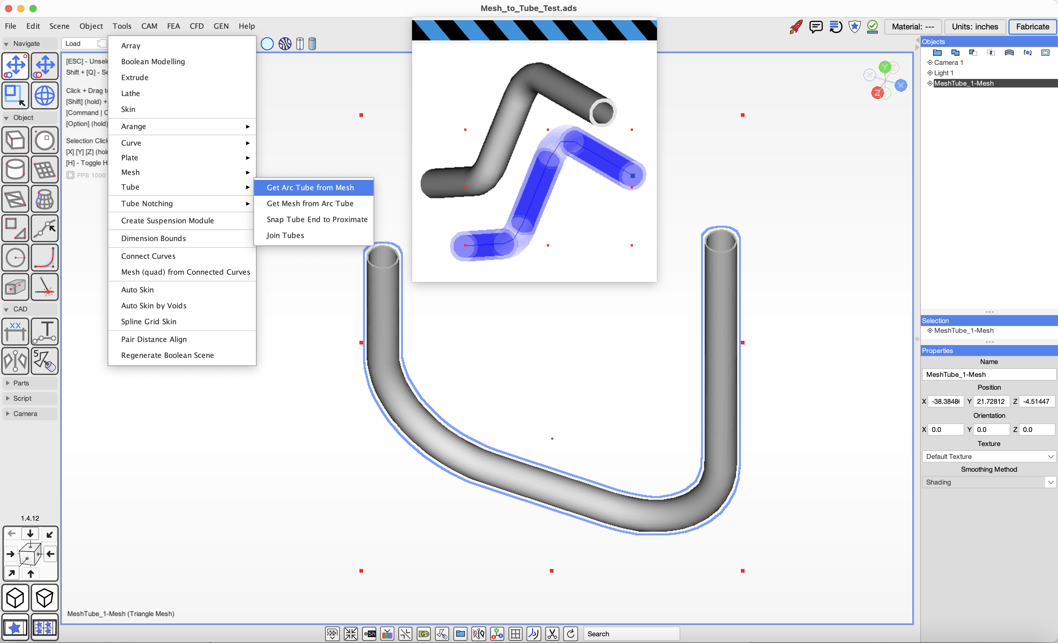 The operation will generate Arc Tube objects which can be notched and exported.
Once a model has been imported you will want to verify the scene units are appropriate. You may need to scale the imported model geometry.
Imported models will still need the intersections and ends to be marked up for notching.
Design analysis features are in progress.
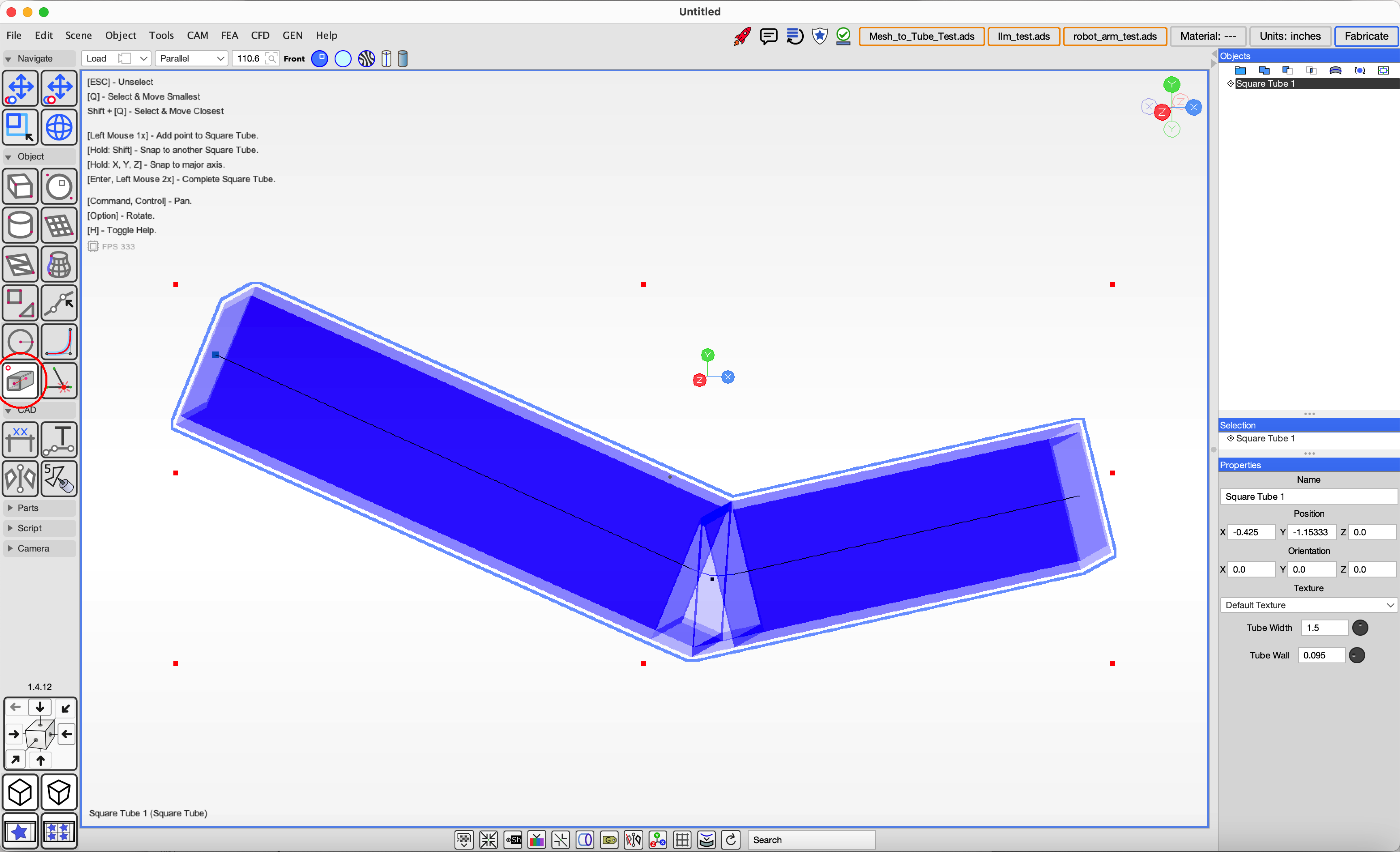
Square tube modelling and GCode export is under development and not production ready but we are making progress to get it ready for upcomming Arma Notching tools.
You can create square tube by clicking on the Square Tube tool in the tool pallete Objects section. Click on the screen at the desired centerline poits and hit the enter key or double click to complete the object.
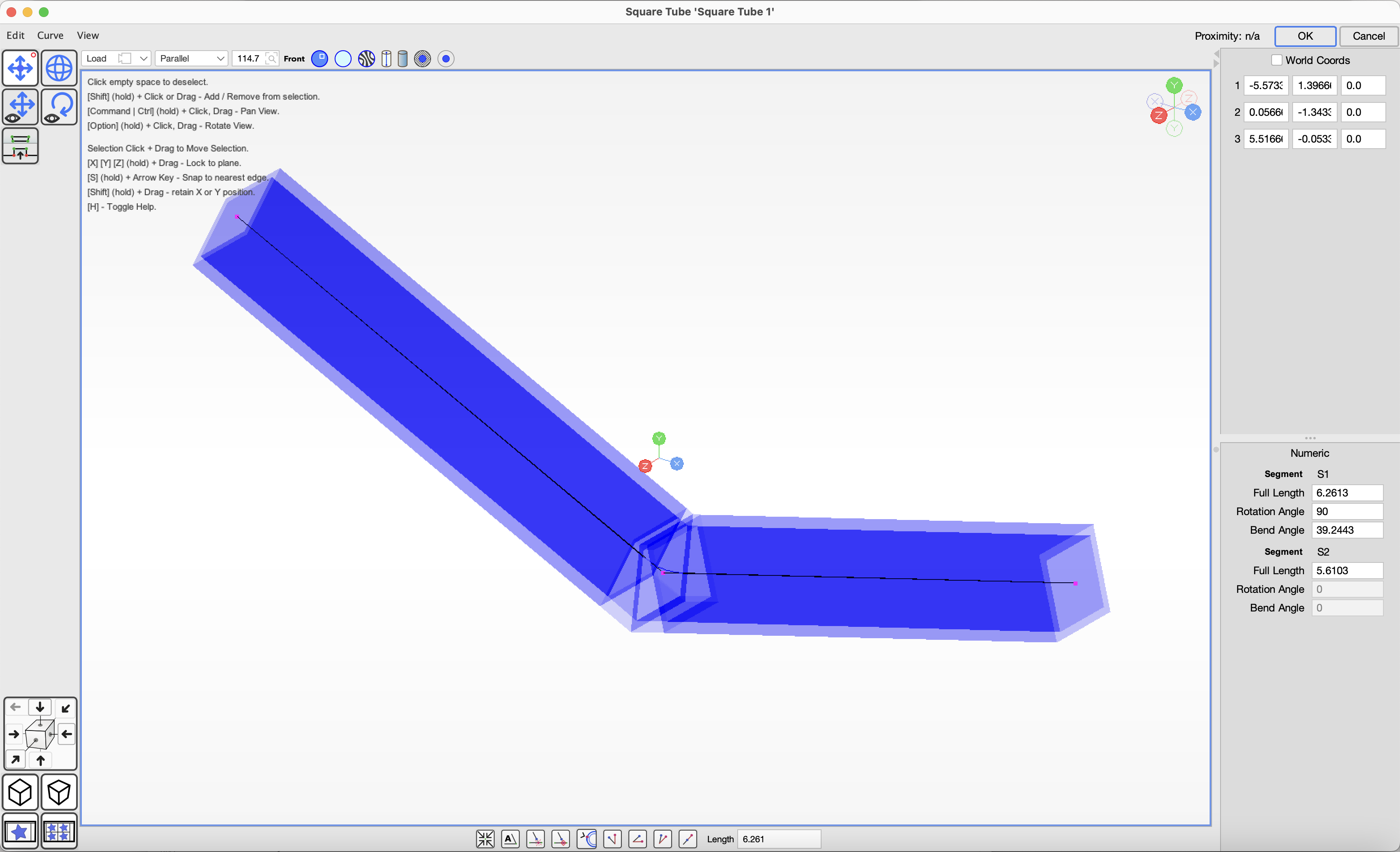
 You can edit the tube by modifying the points by hand or typing in the lengths and bend angles.
 Note that this feature is under development.
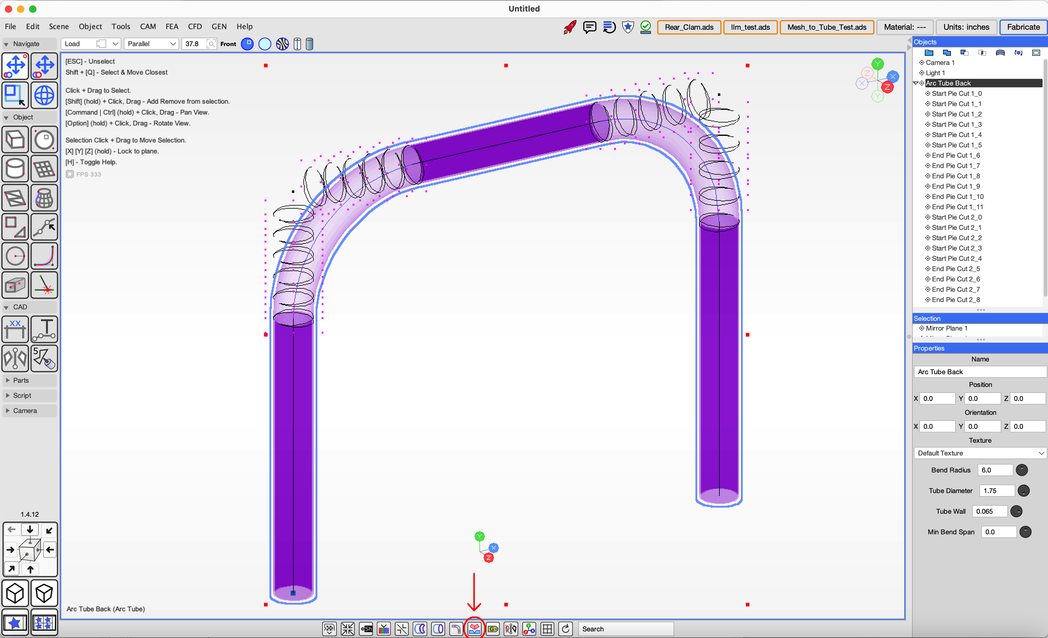
Pie cuts allow you to cut wedges in a round tube so that the tube can be bent to fit
in tight spaces and welded to together to form a continuous shape.
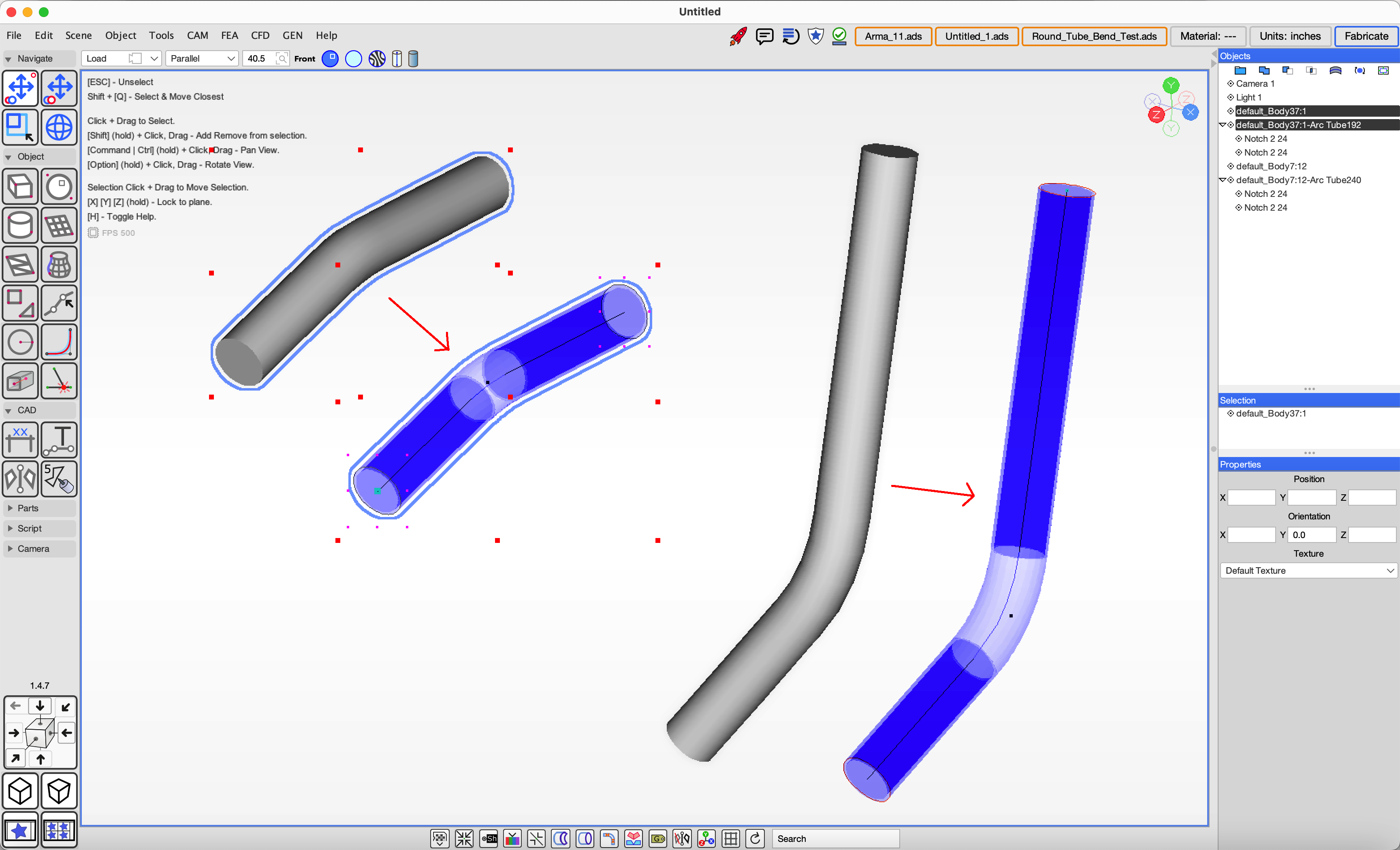
A round tube can be converted to a pie cut by selecting it from the scene and clicking on the 'Pie Cuts' button in the footer bar.
Pie cut tubes display as purple to distinguish from round tube as they have different geometry compensation for bends.
Note that the pie cut notch geometry appear outside the region of the bend, this is a representation that shows how the notches
will be cut on the stock tube when it is straight before bending.
 You can edit the pie cut tube by double clicking the object in the scene or selecting the object and clicking the
'Object', 'Edit Object' menu item.
You can edit the pie cut tube by double clicking the object in the scene or selecting the object and clicking the
'Object', 'Edit Object' menu item.
Placeholder: tutorial content coming soon.
Placeholder: tutorial content coming soon.
Placeholder: tutorial content coming soon.
If you don't have a CNC Tube Bender you can print manual bending instructions from ADS.
Placeholder: tutorial content coming soon.
Placeholder: tutorial content coming soon.
Placeholder: tutorial content coming soon.
Placeholder: tutorial content coming soon.
Placeholder: tutorial content coming soon.
Placeholder: tutorial content coming soon.
We are exploring experimental reasurch into automating machine welding of tube joints. The first step is a new tool that constructs a tool path for information defining how tube joints need to be welded by a 6-Axis robotic arm. The tools to control a robotic arm are not yet available.
To add a weld joint select two intersecting Round Tubes, then click on the Weld Joint button in the bottom fotter bar.
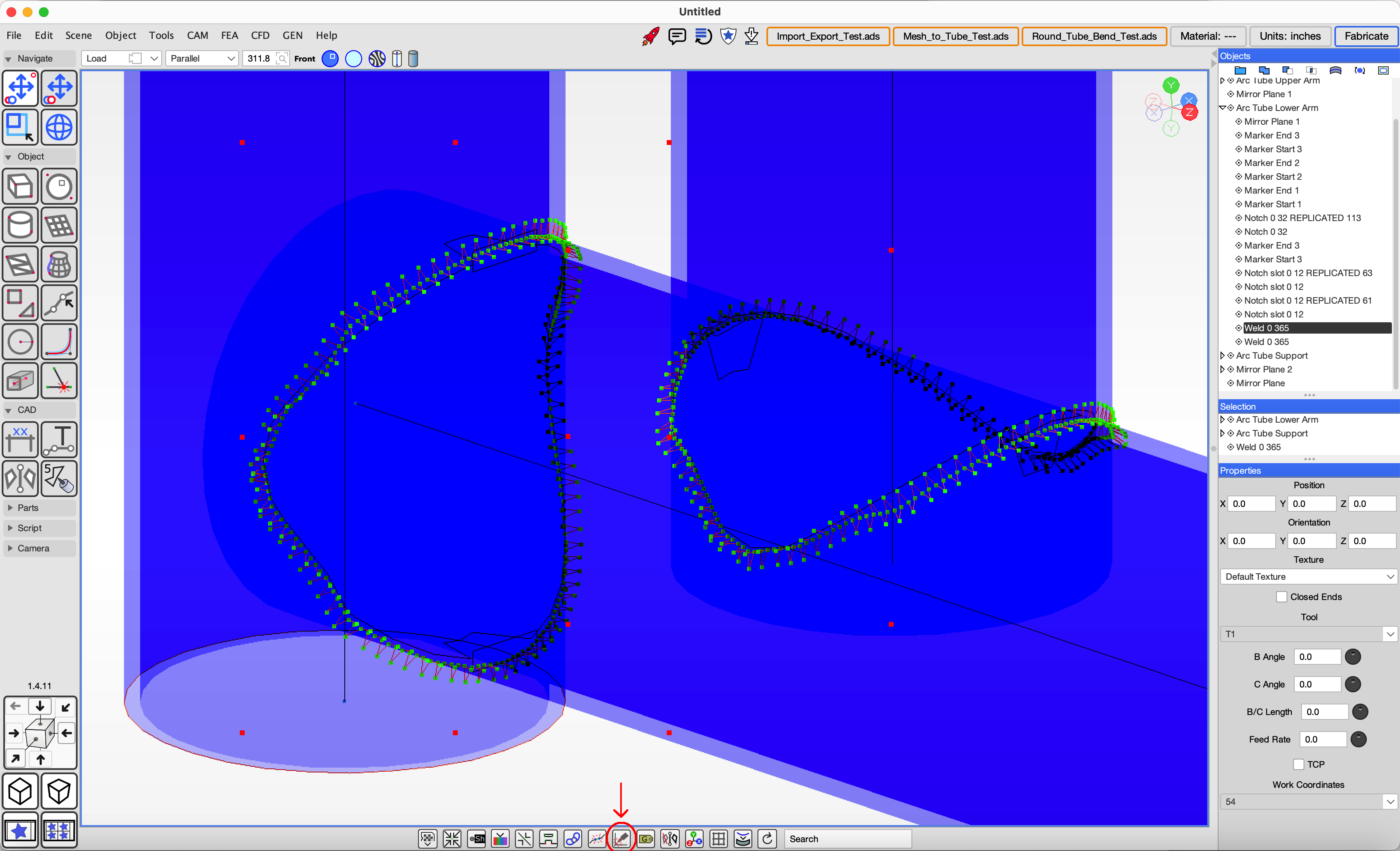 The weld joint is added to the round tube being cut as a child object.
Contact us if you are interested in robotic automation of welding operations.
Placeholder: tutorial content coming soon.
Placeholder: tutorial content coming soon.
Placeholder: tutorial content coming soon.
Placeholder: tutorial content coming soon.
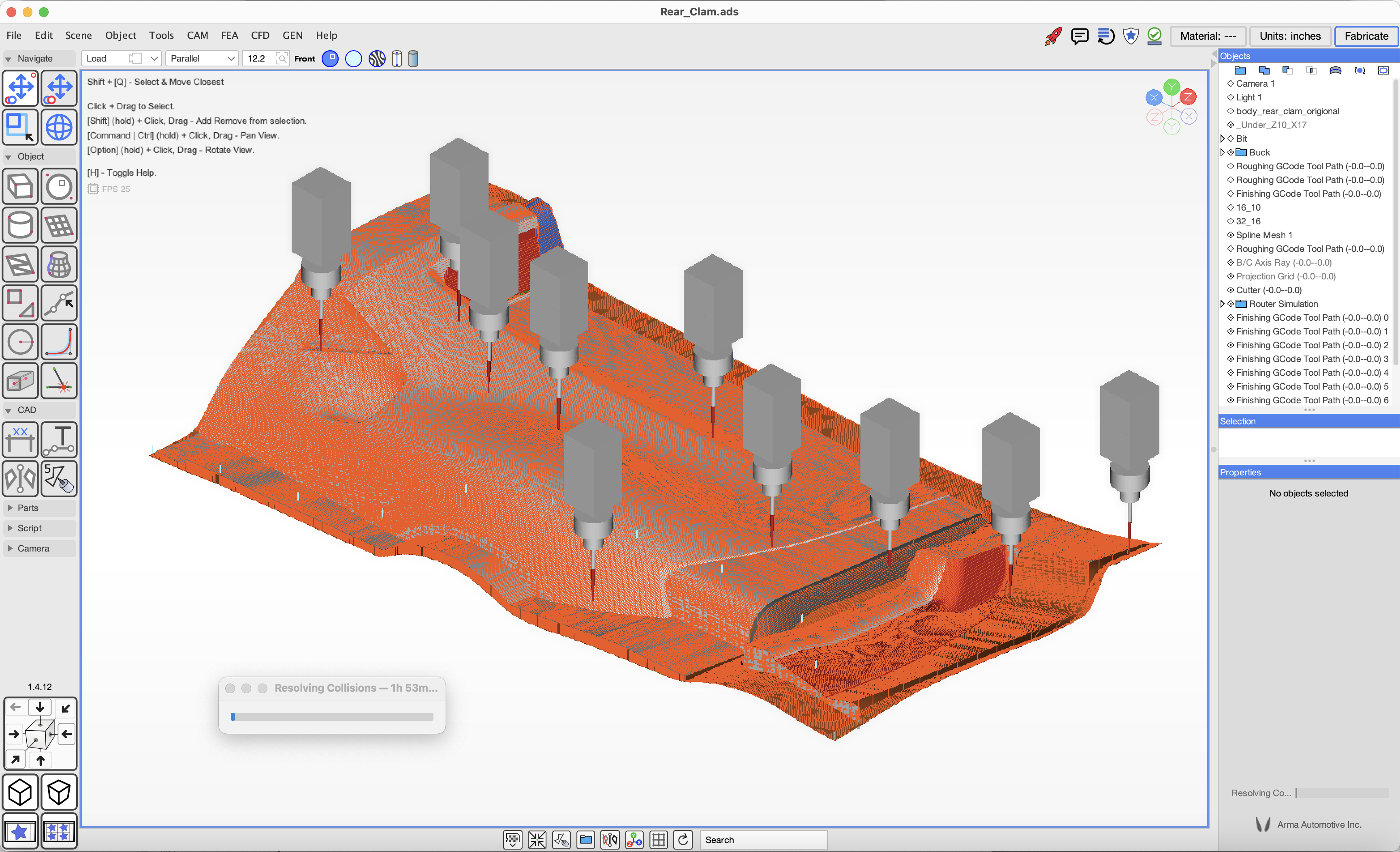
A reliable method for preparing CAD models for routing is to copy final design components to a new ADS file and while selecting each object or group of objects apply a rotation transform to orient them for access to the cutter.
In cases where the part forms a concave shape which would trap mould parts we use a spline mesh or triangle mesh as an intersecting plane to split the part into two. Each part can be assembled to form a complete mould and disasembled to release the part.
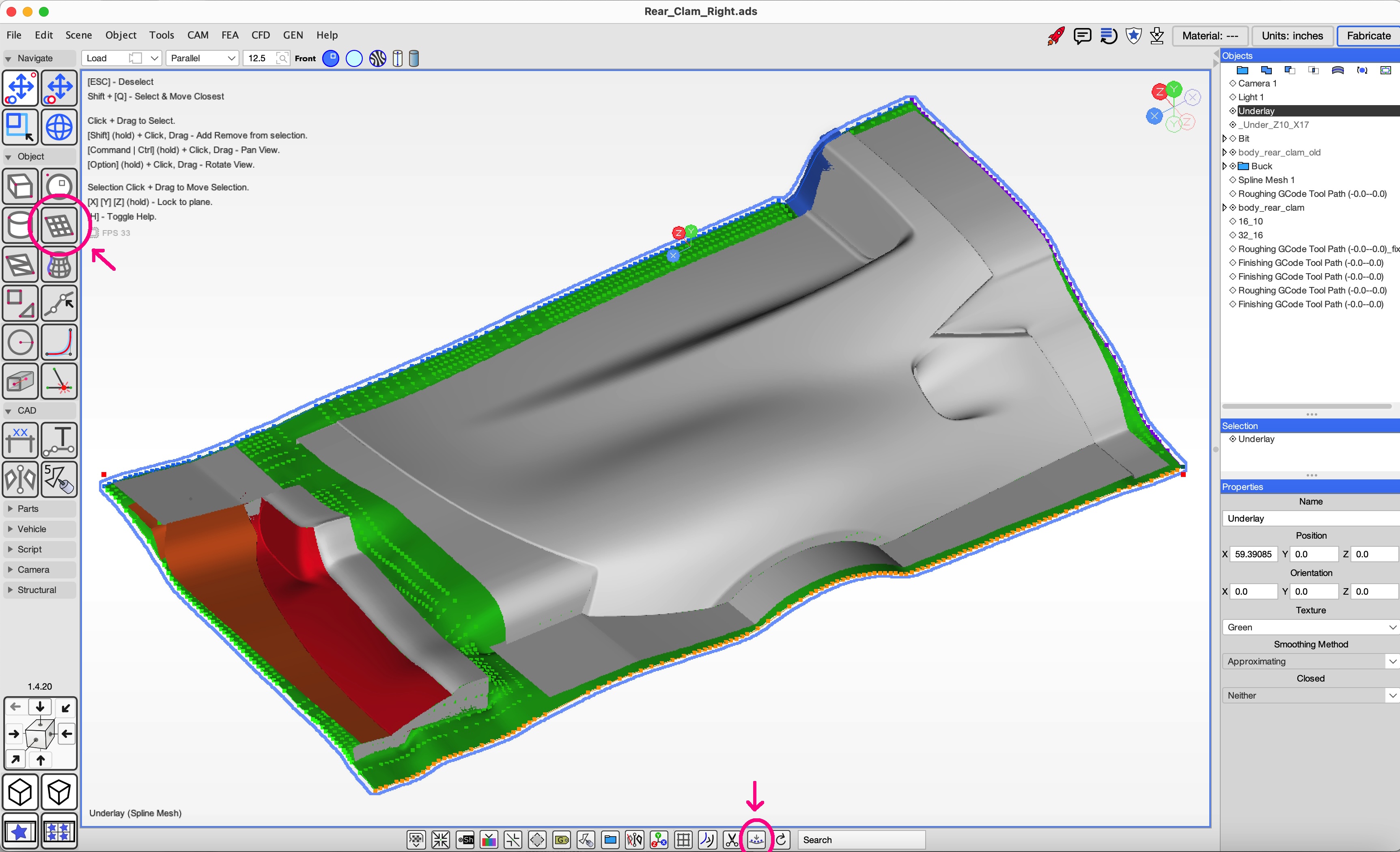
Create an underlay layer using a Spline mesh. Click on the Spline Mesh tool. Click corner points to add a spline mesh to the scene.
Orient it to a horizontal orientation and click on the footer bar button 'Set quare shape size' and type in the width and height values for the cut area.
With the spline mesh selected click on the 'Underlay Mesh' tool in the footer bar. The tool will prompt for an offset distance under the parts to be cut.
After the mesh is positioned check the part edges to ensure the underlay is correct.
The scene viewer has three main modes: Solid View, Transparent View, Contour View. Each viewer window has quick access buttons at the top for each. Solid will render mesh objects with textured colors and gradients. Transparent will render mesh object as a shaded transparent texture to allow visibility of objects behind. Contour shows a light dark zebra pattern to help visualize contours.
Additionally Arc Tube and plate objects can be redered in solid and transparent modes. Transparent mode is useful for design work as the notches and intersections are rendered inside the surface and solid is better for visualizing the final product.
Revolved mesh is a curve object swept around an axis to form a mesh structure. To create a Revolved Mesh object select the "Create Revolved Mesh" tool in the toolbar under the Object group. Click on the scene to add points to the curve shape, double click the mouse to end the curve or hit the enter hey. A revolved mesh object will be added to the scene, when it is selected you can modify the object properties in the lower right side of the screen.
The revolved mesh properties include:
A Revolved Mesh can be converted to a Triangle Mesh if desired.
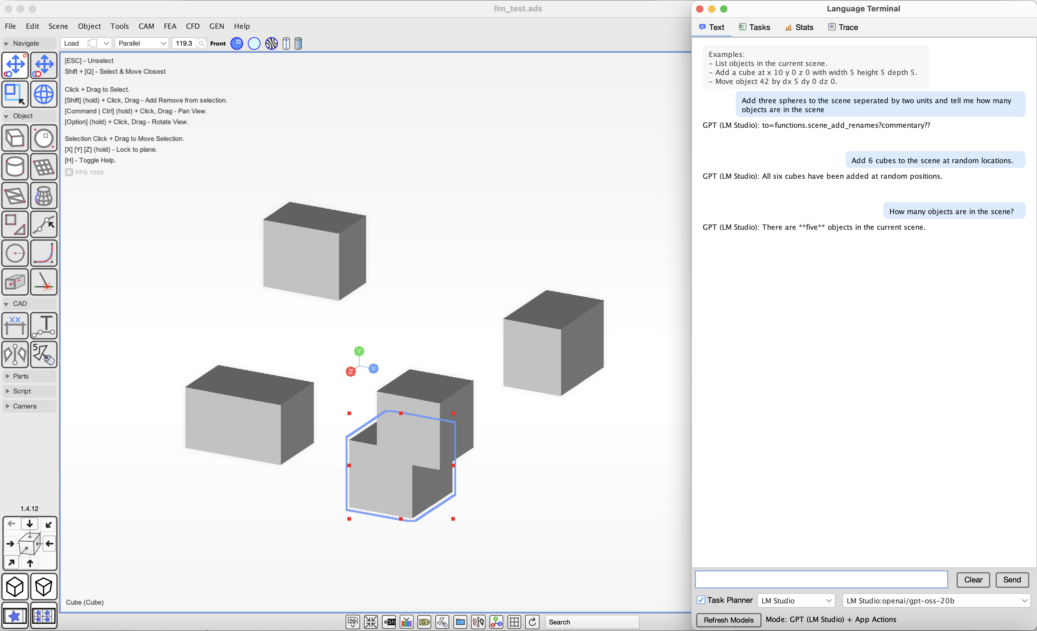
ADS has preliminary support for connecting LLM providers from OpenAI, Anthropic, Google and local models on LM Studio and Ollama.
You will need a vendor key or a local model running on your system to use this feature.
| ||||||||||||||